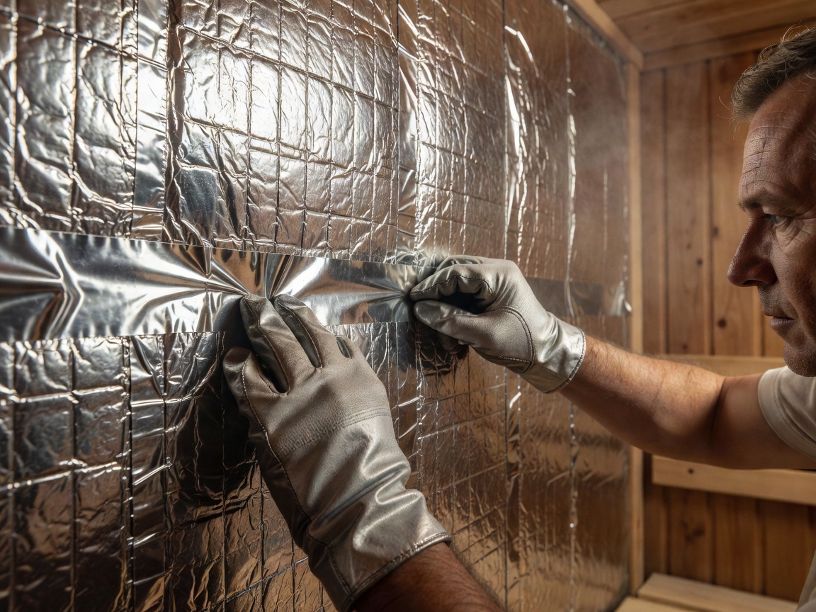
Specialist applying heat-resistant aluminum tape over airtight sauna wall insulation foil
Phase 1 // Envelope

Vapor Tightness: The Aluminum Foil Envelope

When water is ladled over red-hot stones, vapor pressure shoots up instantaneously. If that steam penetrates the wall cavity, it condenses against cool outer brick or concrete, causing hidden structural mold. Standard polyethylene builder plastic degrades and melts at sauna temperatures.

We insist on heavy-gauge kraft-backed aluminum vapor barrier foil installed with 150 mm overlaps. Every seam, staple penetration, and conduit entry must be bonded with high-temperature aluminum tape (rated to 120°C). Over this foil, vertical 22 × 45 mm counter-battens create a continuous rear ventilation gap so the interior wood panelling can dry from both sides.
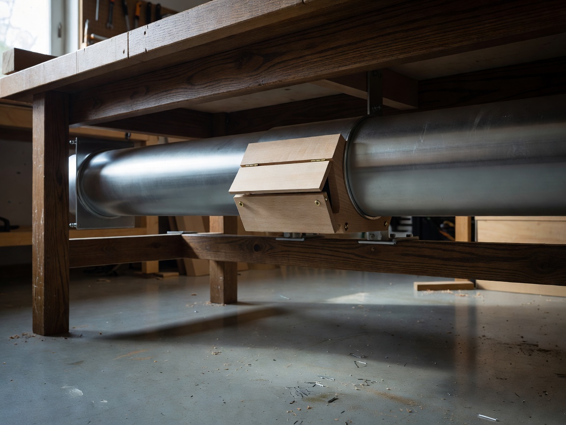
Under-bench mechanical extraction duct and adjustable low-profile timber vent valve
Phase 2 // Airflow

Ventilation Physics: Convection vs. Mechanical Extraction

A suffocating sauna is almost always suffering from poor air circulation, not excessive temperature. When bathers recline, they consume oxygen rapidly; without deliberate airflow, carbon dioxide pools at bench level, triggering headaches and lethargy.

In traditional natural gravity venting, fresh air enters low beneath the heater, warms up, rises, and exits high on the opposite wall. However, in modern airtight homes, we engineer mechanical extraction: fresh air is introduced above or directly behind the heater, while a quiet mechanical duct draws stale air out from beneath the lowest bench. This pulls hot steam down across the bathers' bodies before extracting it.

Certified electrician routing high-temperature silicone cables to a high-capacity heater terminal
Phase 3 // Electrics

Electrical Infrastructure & Three-Phase Feeds

Sauna heaters are demanding electrical consumers. A residential room of 8 to 12 m³ requires an 8 kW to 10.5 kW heater, requiring a dedicated 400V 3-phase supply (or a heavily provisioned 230V single-phase circuit where 3-phase is unavailable in domestic grids).

Standard PVC-coated electrical wiring becomes brittle and fails dangerously in heat-rooms. Every run inside the insulated thermal envelope must be heat-resistant silicone cabling (SIHF), terminated outside the hot zone or inside sealed terminal boxes beneath the cold zone under the lowest bench. All connections must be certified by an accredited electrical engineer.

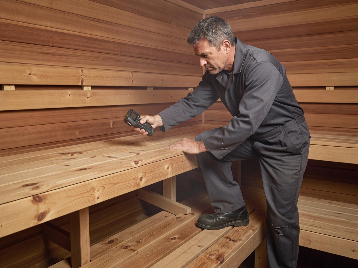
Technician measuring temperature gradient across upper sauna bench with infrared digital pyrometer
Phase 4 // Handover

Commissioning: The 48-Hour Dry Bake & Rock Packing

Before anyone sits on the benches, a rigorous commissioning process must take place. Sauna stones (ideally igneous peridotite or olivine diabase) must be washed clean of quarry dust and stacked loosely around electric elements to allow unobstructed air currents.

We then run an incremental seasoning burn: 2 hours at 60°C, a cooling cycle with doors wide open to vent manufacturing oils from heating coils, followed by a sustained 4-hour bake at 90°C. Only after checking every bench connection for thermal movement and testing temperature sensors for cut-off accuracy is the room released to the client.

The Complete Sauna Construction Sequence

A reliable sauna build is a linear progression. Skipping steps or allowing trades to overlap without thermal coordination invariably causes envelope leaks:

Step 01

Subfloor Waterproofing & Waste Drain

Tile or epoxy basin sloped at 1:100 toward a dedicated low-odor water trap drain. Installation of 100 mm tiled skirting against framing studs to prevent floor wash water from reaching wall timber.

Step 02

Structural Framing & Blocking

Erection of dry C24 timber studs (45 × 95 mm) isolated from concrete masonry by damp-proof membrane strips. Insertion of solid horizontal timber noggins at exact heights for cantilevered bench brackets and heater brackets.

Step 03

Thermal Insulation & Duct Routing

Friction-fitting 70–100 mm non-combustible mineral stone wool (Euroclass A1 fire rating). Rigid metal spiral ducting installed for mechanical intake and exhaust ventilation.

Step 04

Continuous Foil Envelope & Counter-Battens

Wrapping all walls and ceiling in unbroken aluminum vapor barrier with 150 mm taped overlaps. Fixing 22 mm vertical battens to establish the rear ventilation chimney.

Step 05

Interior Paneling & Floating Benching

Blind-nailing tongue-and-groove horizontal or vertical timber with stainless steel brads. Mounting structural bench rails and fitting modular removable seating modules.

Step 06

Heater Rigging & Electrical Certification

Mounting heating appliance, wiring external thermostat sensors at manufacturer-prescribed distances, filling stone chamber, and performing electrical resistance tests.

Professional Scope Notice

While architectural design and timber joinery can be planned in collaboration with interior designers, all 400V electrical runs, high-temperature circuit breaker fittings, and subfloor plumbing connections must be executed and signed off by locally certified professionals according to your national building code (such as UNE in Spain, DIN in Germany, or NF in France).

Contractor Coordination

Need technical coordination for your general contractor?

We provide full mechanical, electrical, and plumbing (MEP) specification packs and framing schematics so your local build team executes every vapor barrier and batten without guesswork.